ESP32-CAM Failed to connect: what to do
The message means the chip did not answer in its bootloader. ESP32-CAM has no USB port of its own: it sits on an ESP32-CAM-MB programmer board or goes through a USB-UART adapter, and GPIO0 must be low when the chip resets. On the programmer board hold IO0, press RST, release IO0 and try again.
Updated November 6, 2026
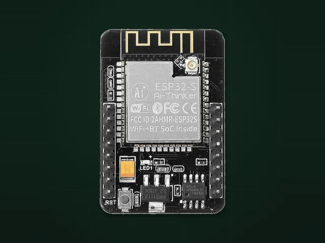
Causes, in the order to check them
- The chip is not in the bootloader. GPIO0 must be low at reset. With a programmer board hold IO0 and press RST. With an adapter wire IO0 to GND, then press RST on the back of the board.
- TX and RX are swapped. Adapter TX goes to U0R, adapter RX goes to U0T. The table below has every wire.
- Not enough power. Feed the 5V pin. The 3.3 V output of FT232R adapters does not give enough current for an ESP chip, the esptool guide warns about it.
- The cable only charges. Try another cable if the port does not appear at all.
- No driver. The programmer board usually has a CH340 chip, see the CH340 driver page. Adapters use CH340, CP2102 or FT232R.
- Another program holds the port. Close Arduino IDE and serial monitors, then reconnect.
- Something is wired to IO12. GPIO12 must be low at power on. Disconnect it and try again.
Wiring for a USB-UART adapter
| Adapter | ESP32-CAM | Note |
|---|---|---|
| 5V | 5V | Power |
| GND | GND | |
| TX | U0R | Signals at 3.3 V: set the jumper on the adapter if it has one |
| RX | U0T | |
| GND | IO0 | Only while flashing |
After flashing
Remove the wire from IO0 and press RST: with IO0 at GND the board stays in the bootloader and your firmware does not start. If the board restarts when the camera or Wi-Fi turns on, power it from a 5 V supply rated for 1 to 2 A.
Boards in this guide
Projects for this board
Prusa Connect ESP32 Cam
Official Prusa firmware that turns an ESP32-CAM into a camera for Prusa Connect: watch your prints from anywhere.No solderingAbout 15 min 2 boardsJust the board
SpotMicro ESP32 Leika
Brain for a 3D printed four-legged robot dog: walking gaits, a 3D model in the browser and a camera stream.SolderingAbout 20 h3 boardsBesides the board: Servo MG996R or similar and 3 moreTasmota
Local smart home firmware: sensors, relays, rules and a web page, with MQTT and Home Assistant support and no cloud.No solderingAbout 15 min4 boardsJust the boardNerdMiner v2
Solo Bitcoin miner as a lottery ticket: the chance of a block is tiny, the stats screen is the fun part.No solderingAbout 10 min 6 boardsJust the board